

This topic explains how to control the size and position of individual diagram nodes of the xamDiagram™ control. For information on how to manage the size and position of the nodes altogether, refer to the Configuring the Layout topic.
The following topics are prerequisites to understanding this topic:
This topic contains the following sections:
The position of a diagram item (node or connection) is determined relative to the coordinate system of the diagram; in this coordinate system, the top-left corner is considered the point of origin and has coordinates of 0, 0. The coordinate numbers represent an offset from the point of origin in pixels. The first number represents the horizontal offset to the right and the second number – the vertical offset in downward direction. The coordinates of a node represent the placement of its top-left corner. For connections, the coordinates are managed by separate properties for their start and end points or are determined by the positions of their snap points) . The following picture represents the coordinate system of a diagram and a node positioned in it at coordinates of 100,100.
The nodes of xamDiagram can be positioned either individually at any location on the diagram’s surface or by applying a layout algorithm (setting available through the Layout property. (For information about the latter approach, refer to the Configuring the Layout topic.)
By default, if no explicit overriding has been applied, a newly created node is displayed at the point of origin of the coordinate system (0, 0).
The size of a diagram node can be controlled explicitly by setting its width and height. There is a default size which depends on its shape. (For reference on default sizes, see Nodes Default Sizes.)
The following table explains briefly the configurable aspects of a diagram node related to its position and size and maps them to the properties that configure them.
You specify the node position by providing the pixel values for the horizontal and vertical placement of the node on the diagram surface to the node’s Position property. The value format is “X ,Y ” , e.g. "75,125” .
The following table maps the desired configuration to the property settings that manage it.
The screenshot below demonstrates node positioning as a result of the following settings:
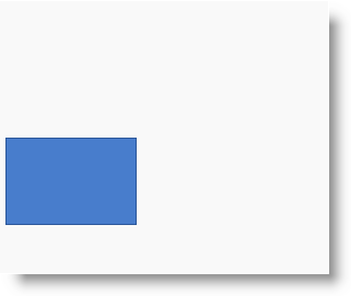
Following is the code that implements this example.
In XAML:
<ig:XamDiagram x:Name="diagram"
               Width="300"
               Height="250"
               Background="#F9F9F9">
    <ig:DiagramNode x:Name="node0"
                    Position="5,125"/>
</ig:XamDiagram>The size of a diagram node can be explicitly controlled by providing values for its Width and Height properties. By default the size depends on the node’s shape (for the pre-defined shapes).
In order to specify whether the aspect ratio of the diagram node should be preserved when resizing occurs, the MaintainAspectRatio property should be set. For all node types apart from square, circle and rhombus, the aspect ratio is not preserved by default. The current aspect ratio of a diagram node could be obtained from the value of the ResizeRatio property.
The following table maps the desired configuration to the property settings that manage it.
The screenshot below demonstrates how the node looks as a result of the following settings:
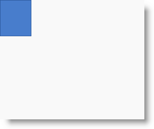
Following is the code that implements this example.
In XAML:
<ig:XamDiagram x:Name="diagram"
               Width="300"
               Height="250"
               Background="#F9F9F9">
    <ig:DiagramNode x:Name="node0"
                    Width="65"
                    Height="75"
                    MaintainAspectRatio="True"/>
</ig:XamDiagram>The following topics provide additional information related to this topic.